Sunday, 9 February 2014

Bantam part 3: BlunderSprint!

I've got the bike in one piece now!

After getting the head bearings in, the swing arm went on. This was the reason I didn't MOT it, it had a lot of free play. Thankfully, the new bushes I put in 4 years ago weren't buggered, either I'd not shimmed up the end float right or the bushes moved sideways a bit. Anyway, for reference: the thick shim (25 thou if I remember right) goes on the left, chain side. Push the swing arm pin through the left bush, the shim, then into the lug in the frame. Tap it thhrough with a soft mallet until it is most of the way through the lug, but not so the end comes out yet. You might want to put a bolt in the end to protect the thread, don't use the ones you want to fit as you'll bend them.
Now, buy a load of different thickness shims, and fit one that only just fits in the right hand side. Or measure the gap with slips and machine one up to suit.
You now need to tap the pin all the way through, but also hold the right shim in place, and avoid trapping it. To do this, push in your old swing arm pin in from the right, so it just goes in the lug, and therefore holds the shim in place. Carry on thrashing the new pin in, it should push the old one out and slip neatly through the shim.

Yes, I forgot to take photos again.


The next area of attention was this dowel. It attaches the rear subframe at the top, and has a bolt going through that both holds it all together and attaches the tank. On some bikes it also attaches the horn, the tax disc, some panniers, spare slippers and a sidecar-a hell of a job for one bolt! Of course, any looseness here will give you a lovely hinge in the middle of your frame. Mine was no exception, the pin had about 10 thou clearance. I put a suitable sized (i.e. found one that fits) reamer down all 3 holes to get them the same, then made a new dowel that is a tight fit in the frame, and close but free fit round the bolt. You can almost feel the handling returning.

So, I had this:


The above object is a location for both the fork spring and rubber gaiter. In standard trim, the spring butts up to the bottom yoke and the gaiter goes on the headlamp ears. I'm binning the ears, so made this replacement. It also has a bit to keep the end of the spring off the stanchion, similar to my previous post.

Last bit on the forks for now. I found that the top bolts were leaking oil whilst riding, so I machined a groove in them for an O ring. Problem solved. This is yet another design flaw they all seem to suffer from.


Gratuitous shot of it coming together.


I'm also trying to hide all the electrics, which will let me do away with the side panels completely. The coil fitted neatly under the tank.


The fuses and key switch in the seat hump


And the reg/rect unit underneath, out in a cooling airflow.


Onward to the engine. The holes in the front mount were worn and a strange size, so I made the top hat washers. Hard to see, but there is a small diameter that fits in the frame hole and bushes it out.


All was going swimmingly well, until someone threw a spanner in the works.

"I'm going to watch Thundersprint this year"

"Why don't you enter your bantam?"

So I did. To begin, I made new lock wirable gearbox drain and filler plugs. The filler has provision to fit a breather hose.


So, having thrown brass swarf everywhere, and got a few kilos in my hands, I went to bed. Night all.

Friday, 24 January 2014

Bantam improving part two: Contains injury.

Here's how to fit taper roller bearings into a bantam steering head.

First, why bother?
The originals are cup and cone ball bearings, which are an utter bastard to assemble. Stick the lower balls in with grease, carefully slide bottom yoke into headstock, dislodge a ball, remove yoke, try again, lose another ball, chuck the hateful bastard thing through the nearest window. When I did it back in 2008, I took the frame and yokes into my bedroom, and assembled it on the soft, carpeted floor. That way, if a ball does drop, it won't bounce off into a corner. If you must insist on the dreadful things, and take your bike inside, put an old shirt down to keep worst of the grease off the floor, and give extra cushioning.

Anyway, as well as being nicer to assemble, taper rollers make the steering much smoother. The rollers have more contact area, so don't pit and notch as readily as balls.


Perhaps most importantly, the quality of replacement cup and cones is dire. I ordered a set for over £40 (seems the going rate). The tracks were obviously turned, not ground, and one bearing hadn't even been finish machined-the track had heat treatment discolouration, and chatter in the track. It's the one on the right in the above photo, the left one is original, showing the shiny ground track where the balls run.

The original bearings are imperial sizes, both of them 1.875" OD. The top ID is 1" dia, the bottom is 1.065". You can't get imperial taper rollers in these sizes, unless you pay someone to tool up for a run of many hundreds. Instead, you can buy metric tapers for a tenner each, and do some metal cutting!

 You will need:

A mill
A boring head
A lathe
An angle plate
Some steel bar stock
Clamps
Plasters
Bandages
A housemate with nowt better to do than patch you up on a saturday night.

I used two 48mm OD x 27mm ID bearings. The size of the inner diameter on the original bottom bearing is very fortunate, as it is 27,05mm in metric. You want an interference fit (i.e. tight, or needs interfering with a hammer). 0,02-0,05mm (or 1-2 thou in imperial) bigger is about right, so a 27mm ID bearing is perfect for this. Thanks, BSA! The top bearing has a sleeve fitted, to make it a 25,4mm, or 1" ID. You can't machine the stem down to 25mm unless you want to cut a new thread in the top and make a new nut.
Are you keeping up with the imperial/metric conversions? Good.

The outer diameter is more of a headache, 48mm=1.890". We need to take around 0.013" out the headstock, to give the 2 thou interference fit. However-if you do this, measure your new bearing first. It should be right, but maybe your micrometer isn't.

The bearing locations must be bored out concentric to each other, or else wonky steering will occur. A fellow machining enthusiast at work suggested this method:

Make or buy a boring head. This tool has a single cutting edge, which is wound out by a screw. You wind the cutting tip out a bit, take a cut, stop the spindle, wind out a bit more, until you've made the hole the right size. Go careful-I very nearly went oversize on the bottom bearing, as it was it needed bearing fit. If you do go too big don't panic, you can get 48,5 OD/27mm ID bearings. In fact, don't put your inner race on the stem until you've got the outer fitted, in case you do need a 48,5mm one!
Here is my home made boring head:

Or you can buy one, which will probably have a nice scale for winding the cutter out. If you're cheap like me, use a knackered centre drill to make your edge.
If you've just made, or not tried, your boring head, take a few trial cuts on some offcuts to see what speeds/feeds are best, and how much it will take off for a given fraction of a turn.


Make a bung on the lathe, to be a tight fit in the top bearing location. Bolt it to the bed of your milling machine. Again, drawings to follow. You'll want it to one end of the bed, you'll see why soon.


The bigger diameter at the bottom is where the bearing location diameter, in the frame, fits. The smaller one is a loose fit (about 0.020" smaller) in the head stock tube, which helps get the frame roughly straight. Note the cut out, to avoid a seam in the tube.

Using a DTI, clock the bung up, so your spindle is dead on its centre, and lock the bed down. Get it as true as possible, you'll not scrap the job by being over accurate!
For the non machinist reading (Hi Mum!), a DTI, or clock, is used to detect small amounts of movement. Each division on this one is 0.001", or a thou, or 0,025mm. It can be used for making sure things are parallel, or concentric, or round, square, flat, etc etc. You've probably worked out that the hand shows the movement.

Put the frame on the bung upside down. Optional extra: Accidentally move the bung, undoing 10 minutes of clocking. Get cross, pull frame off bung. The frame, being a tight fit on the bung, will come loose, allowing you to smack your thumb straight into the freshly sharpened cutter you left in.


Bleed everywhere, get housemate to patch you up, go to bed pissed off.

Anyway: put frame on the bung, like so:


Note how putting the bung at one end gives the frame maximum support.
Clamp up as below


You now need to clock the bottom bearing true to the spindle. This is done by jacking and packing off the angle plate for front/back movement, and between the bed and top tube for side to side movement. Don't move the bed! Again, be as accurate as you can, around 2 thou should be close enough. You may find the original bearing location is warped, damaged or badly machined in the first place. My frame had terrible chatter marks in it, this being built at the same time honda were making CB750s! Also note, it will move when you tighten the clamps, you will probably spend a long time getting it right.

Now it can be machined out. As I say, if you're new to this sort of work go carefully. You might do well to make some plug gauges on the lathe-I'd make a 47.94mm bottom limit one, and about a 48.02 top limit. Aim for bottom limit to just go, and top not to. If the top only just goes in, you should be OK fitting bearing with loctite. If the bearing has any noticeable rattle, you've buggered it. I have some telescopic gauges, which I'm pretty confident with, so I didn't bother.
Take small, slow cuts, winding the cutting edge out barely a breath of a turn. You'll probably want to touch on the bottom of the location seat to clean up (i.e. take metal off all round). As this headstock tube is flared, I'd be wary of going deep, you might thin the wall out.

This should leave you with the bottom bearing ready to fit. Don't put it in yet, though since the bottom bearing takes all the weight, you could probably leave it at that, and have a taper roller bottom bearing and the best bits of the old ball race in the top. Though that does seem a bit half hearted.

The top bearing is more tricky, as the rest of the frame gets in the way. If you had a huge mill, you could repeat the process above with the bung raised up to avoid the downtube. Not having that luxury, I turned the lot sideways.


Despite the Heath-Robinson look, this was successful. However, your mill must have a quill feed-if you wind the bed side to side to take a cut, the straps will pull it all out of line.

Set up is pretty much the same, but this time the bung goes on the angle plate. You'll need a new one too, as it locates in the hole you just bored to 48mm. Again, snug to tight fit.

Note how I've had to give it plenty of length too, to clear the down tube. Make sure you can still fit it all in under the spindle though, it was a tight fit on my mill.
When you put the frame on (after clocking up the spindle), you move it by jacking/packing off the bed to get up/down movement. For side to side, partially tighten the clamp, and knock the frame until it is true. Again, take time and be accurate. This is probably the trickiest bit to get right, so accuracy in the previous steps will lessen the effect of any errors here.


Once machined, tap the outer races firmly home. Use a soft mallet, and if you can make an alumium (or other soft metal) drift, to avoid damage.


Tap the bottom bearing inner home with a clean tube. Box spanners, long sockets and bar stock are handy, just make sure they aren't full of rust, ready to drop in the rollers.
When you grease the rollers, don't just wipe a bit on. Give it a really good rub in, making sure it gets through the cage onto the inner track. Hopefully, you'll not be seeing these again, possibly ever, so give them enough to last.


Job done!

Tuesday, 21 January 2014

Improving BSA bantam heavyweight forks

My first full bike restoration was a 1970 BSA bantam, which my poor apprentice self restored in Dads shed. New to motorcycling, I soon fell in love with the BSA Gold star racers of the 50's, but being a poor appo I couldn't afford one. Still, the bantam does have BSA on the logbook...so my cafe racer project was born.

4 years after finishing it, and 18 months since I last rode it, it's in bits again. There were a few areas I wasn't too happy with, either a result of crap parts, no money, no tools or lack of knowledge. I meant to get it going again last year, got it insured, and found the rear swing arm was wobbly. So now I'm going through it with a precision engineered fine tooth comb, ironing out the flaws to hopefully create the ultimate road going bantam. I hope.

So, on to my first area of improvement: The forks. The 1970 B175 models were fitted with some kind of shortened version of the forks used on various other BSA/Triumph group bikes. I've no idea which, although I think Tiger and bantam cubs got them around that period too. They are pretty beefy for a 175cc bike, with external springs and I forget how big stanchions. They are also flawed in both design and execution.


First up, the seal holder/spring. The seal holder is a deep cup, with an oil seal and a dust seal at the bottom, with the springs resting on top. A rubber gaiter then goes over the spring, supposedly keeping water off. Obviously, it's a british bike, so it doesn't. The top of the gaiter fits over the headlamp ears, which have huge gaps for rain, spray and damp to drop in. The seal then fills with water, and for even greater thrills the spring rubs on the bare ground steel of the stanchion. The first set of stanchions I bought rusted before I even got it on the road, when I fitted this set I filled the seal holder with grease and yet it still rotted. You can see the grotty bit of the stanchion end above too.

For now, I've smoothed down the stanchions. If that doesn't work I'll send them to Philpotts for hard chroming, like they damn well should have been in the first place. If you're restoring a set of these forks, I'd recommend it. New stanchions may well be half the price, but they rot in seconds. Also, I've seen some utterly horrific stanchions for these forks, with a rough turned finish and the taper that locates in the top yoke eccentric to the rest of it by a few mm!
To stop the springs rubbing, I've made some aluminium sleeves. These are a close sliding fit on the stanchion, which will hopefully keep the worst of any dust away. The bore is stepped to accomodate the dust seal lip. Photo below shows the assembly.


 Some people have suggested drilling a drain hole in the seal holders, but I'm unsure. They screw on, so if you rebuild them again the hole at the back may end up at the front. Then you'll get greasy, oily water pouring out (springs still need greasing remember!), which won't look great, particularly at MOT. Plus, it just seems wrong. I might try and seal the gaiters up properly, we'll see.


Next problem is the fork bushes. These look like some kind of oilite material, which is rather like a metal sponge. I'm not sure if the pattern ones I got are too big, or the stanchions ground undersize, but they had a good 8-9 thou clearance, nearly 0.25mm! Which hopefully explains the front end sloppiness the bike had. I've made some new bushes in brass, with a tight fit on the non sliding surfaces and about 2-3 thou (0.05-0.08mm) clearance. You can feel stiff spots at either end of the stroke, I'll probably hone the legs out a bit to even up the wear. Either way, they feel loads better.

I'll post all the drawings for the parts I make once I make them all. Next up: How to fit lovely, better and cheaper metric taper roller bearings in your steering head. Will contain blood, unlike my poor thumb...

Saturday, 31 August 2013

Matrix clutch on a Colchester Chipmaster lathe

I've been setting up my colchester chipmaster at last. It was an absolute dream to run, except the clutch. Pulling the handle engaged it, but as soon as I let go it disengaged. There was no clunk, click or anything to suggest any sort of locking mechanism locking in place, and I was getting pretty fed up. There was no indication of anything thant would keep pressure on the plates, either physically or in the parts book.
I joined the colchester lathes Yahoo group, and immediately found a document that explained how it works. This collar fits on the end of a shaft, and is pulled in and out by the clutch lever. Note the 3 internal lugs:


When you pull the lever, these lugs are supposed to go over these rollers, 3 off, in the ring.


This squeezes the rollers in toward the centre of the shaft, and up the ramps, which forces the two plates apart and puts pressure on the clutch.
However, you can just see there are two splined shafts, one inside the other. The collar fits on the smaller of these, which you can just see poking out in the picture above, and the clutch assembly on the larger. These splines have a different number of teeth!


So, my lathe looked like this. Look closely, and you can see that the lug in the collar is only half over the roller. So, instead of going over the roller and squeezing it in, it just presses against the plate-so the lathe starts, then immediately disengages.


You need to turn both the collar assembly and the collar on their splines (i.e. take off, advance one spline, try it), until the lugs line up with the collars like this. The rollers have been removed for clarity, since they fall out at any opportunity it is easier to line it up before you refit them.

There is a knurled adjusting collar that adjusts the slack in the clutch. You should be able to pull the collar over the rollers with a clunk-if it won't go, back off, if it doesn't clunk, tighten up.

This was one of those utter arsehole problems that seem impossible to solve, so feel free to spread this post about-I might save someone else days of stress and a headstock strip!

Thursday, 25 July 2013

BEV 551-Livery and details

I've been having a good look at that one remaining photo of a working BEV 551. I even bought a copy of Industrial Narrow Gauge Railways of Britain, hoping for a slightly better version.
Here it is again:


First, note A and B. A is a cable running into the battery box, repeated at the other end. No clue as to what for (other than "to carry electricity"), but handy to know it was there.
B is some sort of data plate-maybe the works plate, maybe battery data, could be anything cos I can't read it! Hopefully a better copy of the original would show it up, if I ever find it.

C and D are more useful now though. Note how in oval D, the back of the bufferbeam and part of the frames is just distinguishable in the shadow. It seems to be a lighter colour than the black middle section, which isn't in shadow.
C shows how the buffer beam looks a lighter colour, but with the edges in a darker shade. For reference, here is it built up:

Obviously a junior SGLR member was used to recreate (ish) the other photo!

At first glance, BEV seems to be pure rust, but there are still flecks of paint. Even better,
removing the wheels has exposed areas that are inaccessible to someone giving it a quick tart up, and protected by grease. A quick clean up revealed...


The red in the top right isn't actually the colour I'm looking for. Initially I thought this was it, hence BEV was painted red when I did the top half. I now think it is actually red oxide primer, presumably the result of a quick tart up by a previous owner.
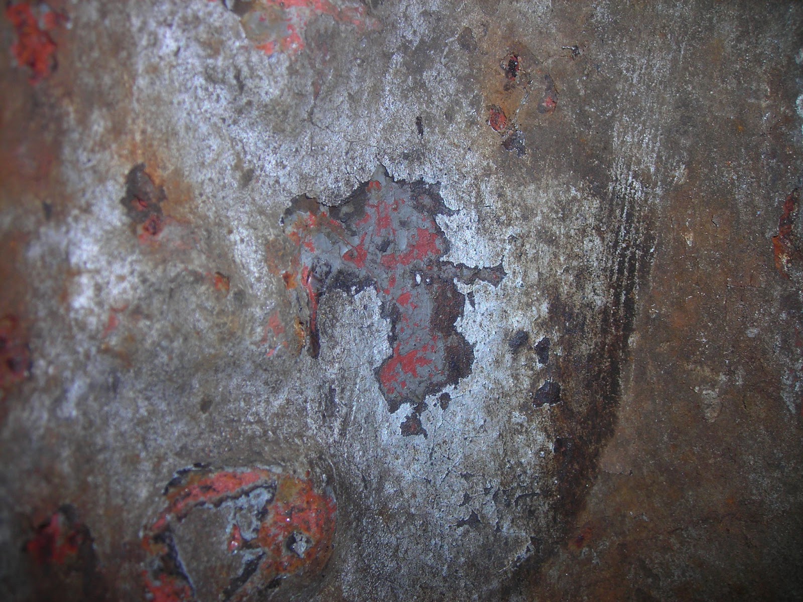
Instead, look at the vague arc going bottom right to top left. That is where the wheel was, and where the mystery painter couldn't reach. The black is old grease, and in the middle...the original Grey! The darker flecks are bare metal.

Further investigation found this grey patch on top of the frame:

So thats the lighter colour probably settled. For me, the patch behind the wheels seals it. Theres no more paint behind or on top of it, I doubt industrial owners would take off wheels for a repaint-if they ever painted it-and I reckon if anyone in preservation took a wheel off to paint behind, it'd either have had a more obvious start made or been left in a million bits until scrapped.

The buffer beam edge that shows dark in the photo threw up this:


Again, red is most likely red oxide.The black in the middle seems to be paint, the small flecks of grey beneath are bare metal. At least, the black flicks off with a knife blade leaving the grey flecks behind.

Finally, the wheels:

In the scraped away patch: Silver seems to be a tart up, with thick layer(s) of black beneath, then grey, then red oxide. Why they originally put primer on the wheels yet none apparently on the frames is a mystery, maybe they couldn't be bothered?

So, it looks like light grey (probably battleship grey) and black may be the colours shown in the old photo. Ironically, I've often said we should paint it grey and black because the picture is in grey and black! Besides, it should look very smart like that.

Tuesday, 16 July 2013

BEV 551 Part 2

We had another BEV day on monday.

First up, we fetched the remaining wheels off. This was much easier than the first, probably because we knew how hard to hit them!
Here is the extractor. There are two threaded holes in the wheel bosses. I used a plate, two bolts and some soft packing. In this case I used aluminium billet, but any softer metal, or even hardwood, should do. The packing protects the axle end.

Jack and support the loco clear of the rail/floor by an inch or two. Put some plywood under the wheel you're about to attack, in case it needs a soft landing. Assemble as shown, then wind the bolts in to get some tension, making sure they don't bottom out in the threaded holes. If they do, put more packing in.
The wheel may need a few knocks with a soft face mallet to break the rust seal. After that, doing up the bolts alternately should pull it off the axle. Once it moves a bit, it comes off the taper and so is only held back by the key.

Next up, we unbolted the axle boxes. Removing the triangular plates behind each wheel:


We found a nut on a fine thread. Note the grub screw locking the nut in place-the sort of thing easily missed until you scrap your axle. Two came out fine, two broke and had to be drilled out. The nuts had to come off, as the slot in the frame for dropping them out is too narrow:

You can see the fill-in piece of metal under the axle end, and that the nut is removed. You can also see the waxy, gritty 80+ year old grease.

Next up, we tackled the axle keep plates. These are two flat bars that run under the frame, and hold pieces of metal that plug the gaps under each axle that allow them to come out. The bar also put back the strength lost by having 4 huge slots in your frame. The bolts here have taken the brunt of derailments and damp, yet we only had to angle grind 3 of them!

By the end of the day, we had this. The axleboxes are held in by one bolt at the top, so we're about ready to drop them out.


Thursday, 11 July 2013

BEV 551 part 1 of millions

This was BEV 551:


Built in 1924 (ish), BEV is an 18" gauge battery electric loco, built for hauling things round factories.  The above is a photo in service, the writing tells you more history. It's a scan from Industrial Narrow gauge Railways of Britain, published by Barton Press.

Many decades later, it looked like this, after arriving from Gloddfa Ganol in wales to Steeple Grange in Derbyshire:


BEV sat under a sheet for a few more years, until a younger, over-optimistic me bought a 49% share in order to start getting it done up a bit.
About a year later, and I had this:


Then work, house and women took over. But at least BEV was kept under cover for the next 5 years.
February this year, I felt I finally have enough room at home to fetch it here and do a bit more. So after a chat with Bob, who owns the other bit, and Dad, who loves moving heavy things and moaning about being asked to do it, most of BEV came to a secret location in [CLASSIFIED].

The painted bits have stayed up the railway for now, so I can spread the chassis over a greater area.
So anyway, BEV arrived, was dumped in the shed and then some bloody enfield got in the way...but monday, work began!

The plan is, roughly, this. First, rip the chassis apart, get it blasted and painted, then reassemble the frames. Next, we overhaul the wheelsets. BEV is so basic it's ridiculous, one motor driving some huge straight cut gears and no suspension at all. So all (!) we need is a good clean, new bearings and some rather pricey gears.
After that, things get a bit murkier. We have the controller and resistance bank, but no motor. Also, if we're fitting a new motor and gears, we might as well pop in some air brakes so it can pull passengers on her triumphant return. Probably in the year I retire, but you never know.


Bit of detail: The staff sticking up is for the brakes, which are removed. The big ugly gears drive a countershaft affair. The motor sits in the middle, sticking out one side. Here's a photo of BEV 640 at the East Lancs Light Railway, thanks to Alan Jones:


So, Bob came over monday, and we took 3 hours to get a wheel off. Not quite Formula 1 territory, but god only knows when they were last off.


Heavy buggers too


This shows the utter pain in the arse we're dealing with. To undo those nuts, you need the wheel off. As far as we can see, dropping out the whole wheelset in the normal way is impossible. Thankfully, you can drop the axles out-I though at first you could only remove that and the gear by splitting the frames


It'll be a long project, but you've got to start somewhere. Interesting change from bikes at any rate. I'm thinking of making up drawings too, and might even have a go at modelling it in 5" gauge. Be useful for air brake design at least. Next work party is this monday, so we might get another one off!